
What Is ScanCOMPONENT?
ScanCOMPONENT is a PC-based offline component programming system for the creation of vision data files from the smallest flip chip and bumped packages to the largest odd form devices. Wafer trays, nozzles, shields, lead frames and feeder tapes can also be imaged, measured and processed. The system includes a calibrated high-resolution color scanner platform combined with a powerful, easy to use, software package.
The Process
Obtain component measurement data by simply placing the desired component on the flatbed scanner, bringing the image into the system and filling in the required fields. This creates an output file that is ready to use, a simple process taking only a few minutes.
Flexibility
Images and related measurement data are stored in ScanCOMPONENT ready to be compared to future revisions or releases of the same component. Different job lots or different sources for the same component can be verified to have the same characteristics in this offline system to avoid interruptions or surprises on the production floor.
Benefits of ScanCOMPONENT
- Accurate: High precision measurement tool eliminates common component programming errors.
- Powerful: Permits offline comparison of substitute components to verify compatibility with existing programs.
- Fast: Helps first article set up and product change over on production systems.
- Flexible: Able to program the smallest components (flip chips) up to the largest components (Odd Form), SMD through hole, etc.
- Eliminate: Using production machines for component teach.
- Easy: Simple step by step procedure.
Why Use ScanCOMPONENT?
ScanCOMPONENT is a powerful, accurate, calibrated measurement tool that is able to capture images of boards, components and processes for documentation purposes.
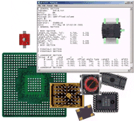
Supports today’s small packages, i.e. BGA; micro-BGA and flip chip components, etc. From the scanned image, the system automatically obtains and generates:
- Exact X, Y location and diameter of balls and bumps
- Lead pitch information
- Lead groups
- Body dimensions
- Direct vision file generation for Fuji SMD3 & Siemens SIPLACE
- Generic vision ASCII files for other suppliers
Technical Specifications*
System Specifications*
- High-Resolution Color Flatbed Scanner, Size A4:(400/1000/1600/2000/2400/3200/4000/4800 dpi)
- Calibrated Accuracy: ± 0.0015” (± 0.0381mm)
- A4-Scanning Bed Area: 8.5″ x 11.5″ (216mm x 292mm)
- Maximum Work Area: 32.0″ x 32.0″ (813mm x 813mm)
Computer*
- Multi Core Processor – 3 GHz
- 1 TB 7200 RPM HD, 8 – 16 GB RAM
- CD/DVD ROM – for archive purposes
- Flat Panel Monitor (17” or larger)
- Ethernet connection
- Windows 10 – 64-Bit
- 2 available USB ports – USB2 or USB3
*Recommended customer supplied minimum PC requirements.
Additional System Components
- Precision Glass Calibration Grid
- Software Protection Key
- Scanning Accessory Package
The following are trademarks of the indicated companies: Gerber, Ucamco N.V.; Windows 10, Microsoft®; ScanCAD™ and ScanINSPECT VPI™ are trademarks of ScanCAD International, Inc. *All specifications and designs subject to change without notice.*
Friendly, Flexible, Innovative & Global
ScanCAD International, Inc. continues to flourish and evolve to successfully meet ever-changing technology requirements.
All ScanCAD products were developed at the request of its customers, therefore your comments and suggestions are welcome.