

What is the Schematic Generation Lite Module?
The Schematic Generation Lite Module is a total EDA/ECAD software package of seamlessly integrated, task-oriented modules covering all stages of the electronic circuit design process – from capturing the idea of a circuit in the form of schematic diagram to generating a full set of documentation for manufacturing and assembling of PCBs.EDWin is integrated into ScanCAD’s family of reverse engineering products to provide schematic generation and CAD upload capabilities.
It is integrated into ScanCAD’s family of reverse engineering products to provide schematic generation and CAD upload capabilities
Feature Highlights
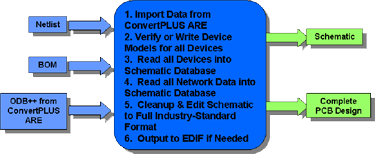
- Schematic editor can import data from the ScanCAD family of PCB re-engineering products to create a new schematic or edit an existing one.
- Automatic operations for placing, packing and routing components.
- Export schematic DXF to AutoCAD format or to a PDF output.
Layout Editor
- Design the PCB layout of a circuit
- Automatic functions to simplify the process of renumbering components and routing
- Use the thermal analyzer to identify potential thermal problems
- The electromagnetic analyzer will show the distribution of electric field energy routed on a PCB
General Features
Conversion manager for Library conversion, database conversion and EED III Conversion.
Waveform viewer that may be used to generate results in the form of diagram for simulators.
Subcircuit adapter allows existing SPICE subcircuits to be converted into an EDSpice format.
Model parameter editor simplifies the management and creation of model libraries.
List generator utility allows generation of a list containing required details of the component library.
Netlist import and export eases the transfer of information of all nets or connections involved in a circuit. The information can be transferred to and from third party software. Formats that are supported include: JEDEC, CUPL, XILINX, ALTERA and more.
SPICE Netlist import allows the import of circuit and subcircuit files. The schematic diagram is generated by converting the imported file data to the project. The parameters and model parameters are set during conversion. The circuit and parameters are set for various analyses as specified in the circuit file.
Schematic DXF Export is an application that allows the user to export the schematic graphic to AutoCAD DXF format.
Layout DXF Export allows export of layout graphics to AutoCAD DXF format.VHDL editor has been included to describe the behavior of digital systems.
VHDL Editor has been included to describe the behavior of digital systems.
VHDL model generators allow conversion of VHDL source files to models for simulations.
Schematic Editor
- Create a schematic of a new circuit or an existing design by importing data
- Simple editing of electrical connections, components and routing
- Export schematics in an Autocad DXF format
The following are trademarks of the indicated companies: Gerber, Ucamco N.V.; Windows 10, Microsoft®; ScanCAD™ and ScanINSPECT VPI™ are trademarks of ScanCAD International, Inc. *All specifications and designs subject to change without notice.*
Friendly, Flexible, Innovative & Global
ScanCAD International, Inc. continues to flourish and evolve to successfully meet ever-changing technology requirements.
All ScanCAD products were developed at the request of its customers, therefore your comments and suggestions are welcome.